Steam Turbine - Part I (Introduction & its major types)

Steam turbine is a type of turbomachine which is an assembly of nozzles and blades. It converts a part of the energy of high temperature and high-pressure steam (Enthalpy of steam into Kinetic in nozzle) into mechanical energy (or shaft work). The operation of steam turbine completely depends on the dynamic action of the steam expanding in nozzles.
The steam turbines are used for the
generation of electricity in steam power plants varying from 1 MW to 1500 MW
capacity. These are also used for marine propulsion. The steam turbines operate
at very high speed (up to about 40,000 rpm) and are able to give efficiency
about 40% which is higher than the other power producing devices. Because
of its ability to develop tremendous power within a comparatively small space,
the steam turbine has superseded all other Prime Movers, except hydraulic
turbines, for generating large amounts of electricity and for providing
propulsive power for large, high-speed ships. Today, units capable of
generating more than 1.3 million kilowatts of power can be mounted on a single
shaft.
The
steam expands in a turbine from high pressure to low pressure (below the
atmospheric pressure). Steam cannot be exhausted to atmosphere at a pressure
lower than the atmospheric pressure. This is made possible by using an
additional unit called condenser. A steam condenser is a closed vessel in which
vacuum is maintained and the exhausted steam is condensed by extraction of
heat. About 50% to 60% of the heat energy associated with steam is lost in a
steam condenser.
Cooling water supplied to the condenser for the condensation of steam becomes hot. The cooling towers and the cooling ponds are used to cool this hot water coming out of the condenser so that the cooled water can be reutilized in the condenser again. Small power generation unit uses air as cooling medium instead of water, Air cooled condenser will be preferred where water usage is limited.
Classification of Steam Turbines
On
the basis of the principle of operation (mode of steam action within turbine),
it can be divided into two major types
1) Impulse Turbine
2) Reaction Turbine (Impulse reaction turbine)
The main distinction is the manner in which the steam is expanded as it passes through the turbine.
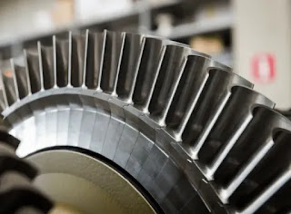 |
| Impulse Turbine Blade profile |
 |
| Reaction Turbine with first stage Impulse blade and next stage reaction blade profile |
Impulse Turbine
In impulse turbines, the steam expands through the nozzle, where most of
the pressure potential energy is converted to kinetic energy. The high-velocity
steam from fixed nozzles impacts the blades changes its
direction, which in turn applies a force. The resulting impulse drives
the blades forward, causing the rotor to turn. The main feature of these
turbines is that the pressure drop per single stage can be quite large,
allowing for large blades and a smaller number of stages. Except for low-power
applications, turbine blades are arranged in multiple stages in series, called
compounding, which greatly improves efficiency at low speeds.
Modern steam turbines frequently employ both reaction and impulse in the same unit, typically varying the degree of reaction and impulse from the blade root to its periphery. The rotor blades are usually designed like an impulse blade at the rot and like a reaction blade at the tip.
 |
| Impulse reaction Blade |
 |
| Working Principle animation |
Reaction Turbine
The reaction turbine is composed of moving blades (nozzles)
alternating with fixed nozzles. In the reaction turbine, the steam is
expanded in fixed nozzles and also in the moving nozzles. In other words,
the steam is continually expanding as it flows over the blades. There
is pressure and velocity loss in the moving blades. The moving blades have a
converging steam nozzle. Hence when the steam passes over the fixed blades, it
expands with a decrease in steam pressure and an increase in kinetic energy.
An aerofoil shaped profile helps steam flows faster on one side than the other side. Therefore, a greater pressure on one side than the other side of the blade. This difference in pressure produces the lift (reaction
force), which helps for rotation.
 |
| Reaction force on Blade |
In reaction turbines, the steam expands through the
fixed nozzle, where the pressure potential energy is converted to kinetic
energy. The high-velocity steam from fixed nozzles impacts the blades
(nozzles), changes its direction, and undergoes further expansion.
The change in its direction and the steam acceleration applies a
force. The resulting impulse drives the blades forward, causing the rotor to
turn. There is no net change in steam velocity across the stage but with a
decrease in both pressure and temperature, reflecting the work performed in the
driving of the rotor. In this type of turbine, the pressure drops occur in
several stages because the pressure drop in a single stage is limited.
The main feature of this type of turbine is that
the pressure drop per stage is lower in contrast to the impulse turbine,
so the blades become smaller, and the number of stages increases. On the
other hand, reaction turbines are usually more efficient, i.e., they have
higher “isentropic
turbine efficiency.” The reaction turbine was invented by Sir
Charles Parsons and is known as the Parsons turbine.
In the case of steam turbines, such as would be
used for electricity generation, a reaction turbine would require
approximately double the number of blade rows as an impulse turbine
for the same degree of thermal energy conversion. While this makes the reaction
turbine much longer and heavier, the overall efficiency of a reaction turbine
is slightly higher than the equivalent impulse turbine for the same thermal
energy conversion.
Modern steam turbines frequently employ both reaction and impulse in the same unit, typically varying the degree of reaction and impulse from the blade root to its periphery. The rotor blades are usually designed like an impulse blade at the rot and a reaction blade at the tip.
 |
| Impulse Reaction Blade |

|
Impulse Turbine |
Reaction Turbine |
|
The high-velocity steam from
fixed nozzles impacts the blades changes its direction, which in
turn applies a force. The resulting impulse drives the blades
forward, causing the rotor to turn |
An aerofoil shaped profile helps steam flows
faster on one side than the other side. Therefore, a greater pressure on one
side than the other side of the blade. This difference in pressure produces
the lift (reaction force), which helps for rotation. |
|
Steam completely
expands in the nozzle itself. Hence its pressure remains constant on both
ends of the moving blades |
Fixed blades arrangement
helps to act as nozzle and also steam expands in both fixed and mobbing blades
continuously as it passes over them. Hence pressure drop occurs gradually and
continuously over both the type of blades |
|
Blade passage is
of constant cross section as there is no expansion of steam |
Blade passage is
of variable cross section (converging type looks like aerofoil) |
|
Pressure remains
constant in moving blades the relative velocity of steam passing over the moving
blade remains constant |
Continuous
expansion of steam means relative velocity in moving blade increases |
|
Blades are symmetrical
profile type; hence the manufacturing of blade is simple |
Blade shapes of aerofoil
and non-symmetrical type, hence the manufacturing of blade is difficult |
|
Because of the
large pressure drop, the steam speed and the running speed are high |
Due to small
pressure drop, the steam speed and running speed are low |
|
Because of the
large pressure drop on the nozzle, the number of stages is less and the size
of the turbine for reference power output is comparatively less |
Because of small
pressure drop in each stage, the number of stages is more for the same
pressure drop. Hence the size is large and these turbines are multi stage
turbines |
|
It occupies less
space per unit power |
It occupies more
space per unit power |
|
Suitable for smaller
power generation |
Suitable for
larger power generation |
|
The steam may or
may not be admitted to the whole circumference |
The steam must be
admitted over the whole circumference |
|
The direction of
steam flow is radial to the direction of turbine wheel |
The direction of
steam flow is radial and axial to the turbine wheel |
The
steam turbine can also be further classified on the following basis,
On the basis of direction of flow:
Radial flow turbine
Axial flow turbine.
On the basis of method of compounding
Velocity compounded turbine
Pressure compounded turbine
Pressure-velocity compounded turbine.
On the basis of number of stages
Single-stage turbine
Multistage turbine
On the basis of position of shaft
Horizontal shaft turbine
Vertical shaft turbine
On the basis of pressure of steam at the inlet
Low pressure steam turbine
High pressure steam turbine
On the basis of exhaust condition of steam
Condensing turbine
Non-condensing turbine.
Compounding of turbines, condensing, Non condensing and other type of turbines will be discussed on next topic. Each turbine parts, its accessories, basics instrumentation and control, basic electrical related to steam turbine, calculations will be discussed on subsequent topics.
Bye 👋👋... See you all in next topic
If you like the content, please share and follow us on the social media platforms.. Link below


Good content
ReplyDelete